How to Test Crankshaft Sensor with Multimeter
Dec 12, 2023 View: 6911
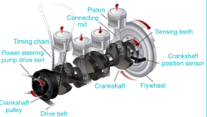
To achieve precise control over ignition and injection timing, it is crucial for the engine to accurately determine the position and operational status of each cylinder. This determination heavily relies on two key sensors: the crankshaft position sensor (Crankshaft Position Sensor) and the camshaft position sensor (Camshaft Position Sensor). The crankshaft position sensor, also referred to as the engine speed and crankshaft angle sensor, plays a pivotal role in collecting the engine's rotation angle data, enabling the retrieval of engine speed and the position of each cylinder.
Concurrently, the camshaft position sensor, also known as the cylinder sensor, integrates with the crankshaft position sensor to determine the working status of each cylinder throughout the intake, compression, power, and exhaust phases. This sensor's signal facilitates the synchronization of injection and ignition control, allowing for sequential injection, precise ignition timing control, and effective explosion control.
During engine startup, when power is supplied and ignition initiated, rapid synchronization of the Engine Position Module (EPM) is essential. This synchronization ensures the prompt release of fuel injection and ignition signals, ultimately culminating in a successful engine start. In summary, the seamless combination of the crankshaft position sensor and camshaft position sensor is fundamental to achieving comprehensive control over sequential injection, ignition timing, and explosion management, contributing to optimal engine performance.
How to Test Crankshaft Sensor with Multimeter
The crankshaft position sensor, commonly referred to as the CKP sensor, plays a crucial role in supplying the engine control module (ECM) with precise data regarding the crankshaft's position and speed. This extracellular matrix of information is instrumental in determining the accurate timing of fuel injection and ignition. A malfunctioning crankshaft position sensor can result in various engine performance issues, such as misfiring, stalling, and diminished fuel efficiency.
Testing the crankshaft position sensor enables the early identification of potential issues, preventing them from escalating into more significant problems. Regular testing helps catch early signs of sensor failure, such as erratic readings or voltage fluctuations. This proactive approach can save you from expensive repairs and unexpected breakdowns on the road.
Security Considerations
Before initiating the testing process for the crankshaft position sensor, it is crucial to adhere to safety precautions and use the necessary tools to protect yourself and your vehicle. Here are some guidelines to follow:
Disconnecting the Battery: Begin by disconnecting the negative pole to ensure safety and prevent electrical accidents. This precaution is essential during the testing process to avoid any accidental damage to the sensor or other electrical components.
Wear Protective Equipment: It is recommended to wear goggles and gloves when working on the vehicle to shield your eyes from debris or chemicals and prevent damage to your hands.
Let the Engine Cool: Ensure the engine is cool before testing the crankshaft position sensor. Working on a hot engine poses risks and increases the likelihood of burns.
Necessary Tools
Now that safety considerations are covered, let's discuss the essential tools required for testing the crankshaft position sensor:
Multimeter: An indispensable tool for testing the electrical characteristics of the sensor, allowing measurement of voltage, resistance, and continuity. These measurements are critical for diagnosing any issues with the sensor.
Wiring Diagram: Specific to your vehicle make and model, this diagram helps identify the correct wires for connecting to the crankshaft position sensor, aiding in locating the sensor and understanding its electrical connections.
Socket Set and Wrench: Depending on the sensor's location, a socket set and wrench may be necessary to remove components obstructing access to the sensor, facilitating efficient testing.
Following these safety instructions and using the right tools empowers you to test your crankshaft position sensor confidently. In the next section, we will delve into the step-by-step process of testing the sensor using a multimeter.
1. Disconnect the Sensor
Before testing the CKP sensor, it is essential to disconnect it from the vehicle harness to eliminate interference from other components. Follow these steps:
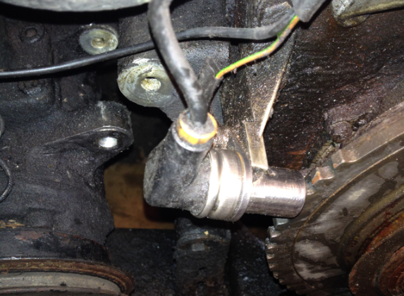
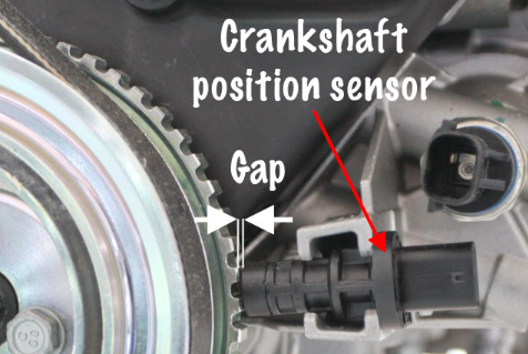
Locate the CKP sensor, typically found near the crankshaft pulley or flywheel.
Carefully disconnect the sensor from the electrical connector. Depending on your BMW model, you may need to remove a protective cover or use a tool to release the connector.
2. Set up the Multimeter
To test the CKP sensor, you'll need a multimeter capable of measuring resistance, voltage, and other electrical parameters. Follow these steps to set up your multimeter:
Set the multimeter to resistance or ohm (Ω) mode for measuring sensor resistance.
Connect the multimeter leads to the appropriate CKP sensor terminals: one for the signal wire and one for the ground wire. Refer to your vehicle's service manual or wiring diagram for the correct terminal identification.
3. Test Resistance
Checking the resistance of the CKP sensor can indicate its proper functioning. Follow these steps:
Connect the multimeter leads to the CKP sensor terminals.
Observe the multimeter reading. Resistance values will vary based on the CKP sensor and air temperature. Consult your vehicle's service manual for the correct resistance range.
Compare the measured resistance to the specified range. If it falls within the recommended range, the CKP sensor may be faulty and should be replaced.
4. Test Voltage
In addition to resistance, test the voltage output of the CKP sensor to ensure it generates the correct signal. Follow these steps:
Set the multimeter to voltage (V) mode.
Connect the multimeter leads to the CKP sensor terminals.
Start the engine or use a scan tool to simulate engine rotation.
Observe the multimeter reading; the voltage should fluctuate as the engine rotates. Refer to your vehicle's service manual for the correct voltage range.
If the voltage output is outside the specified range or does not fluctuate, the CKP sensor may be faulty and requires replacement.
5. Check for Damage
Inspect the CKP sensor for any visual damage, such as cracks, corrosion, or loose connections. If damage is evident, replace the CKP sensor.
6. Reconnect the Sensor
After testing, reconnect the CKP sensor to the vehicle's wiring harness:
Align the electrical connector with the sensor terminals.
Gently push the connector into place until it clicks or locks.
Ensure the connector is securely attached to the sensor.
By following these steps, you can effectively test the CKP sensor on your BMW. Always refer to your vehicle's service manual for specific instructions and values. If you are unsure or uncomfortable with the testing process, seek assistance from a professional mechanic.
Types of Crankshaft Position Sensors
Crankshaft position sensors can be categorized into three main types based on their operational principles: magnetoelectric, Hall, and optoelectronic.
Magnetoelectric Type: This sensor operates on the principles of electromagnetic induction. Changes in magnetic flux resulting from variations in rotational speed are converted into electrical signals to determine the crankshaft position and rotational speed. As the signal disk rotates, the magnetic field intensifies when the signal disk's convex teeth align with the electromagnetic coil. Conversely, as the convex teeth move away from the coil, the magnetic field weakens. This alternation induces an electromotive force in the inductive coil, and its frequency and amplitude linearly increase with engine speed. Notably, this sensor doesn't necessitate additional power from the ECU, boasts a straightforward design, and is cost-effective, making it widely employed.
Hall Type: Leveraging the Hall effect, this sensor employs a signal generator. When current (I) passes through a thin gold foil within a magnetic field (B) at a right angle to the field's direction, Hall voltage (UH) is generated on both sides of the gold foil. The Hall voltage's magnitude is directly proportional to the current passing through the gold foil and the magnetic flux density. In operation, when the blades on the signal disk intersect the air gap between the permanent magnet and the Hall component, the blades interrupt the Hall trigger's magnetic field. Consequently, no Hall voltage is generated, leading to no output signal. Conversely, when the notched part of the impeller enters the air gap, the Hall voltage increases, and the sensor outputs a voltage signal.
Optoelectronic Type: Comprising components such as light-emitting diodes, gratings, and photosensitive diodes, this type utilizes light beams emitted by the LEDs. These beams pass through a grooved grating disk that synchronously rotates with the crankshaft. The photosensitive diode receives the transmitted light and converts the optical signal into an electrical output signal.
Final Words
In conclusion, testing a crankshaft sensor with a multimeter is a critical diagnostic step in ensuring the optimal performance of your vehicle's engine. The accuracy of the crankshaft sensor is paramount for precise ignition timing and fuel injection, directly impacting overall engine efficiency. Throughout the testing process, we have covered essential steps, from disconnecting the sensor and setting up the multimeter to examining resistance and voltage.
Read More:
What Happens If You Disconnect Throttle Position Sensor
Crankshaft Position Sensor Location
Temporary Fix for Crankshaft Position Sensor
How to Test Crankshaft Sensor with Multimeter
Where Is the Knock Sensor Located
How to Start a Car with a Bad Crankshaft Sensor
How to Start a Car with a Bad Crankshaft Sensor
How does the Oxygen Sensor OSS-2 Effectively Improve Vehicle Exhaust Pollution Emissions
Where are Radar Sensors on Mercedes
How Many Sensors Are In a Car【Types & Functions】
How to Delete O2 Sensors from ECM
How Many O2 Sensors Does a Car Have
4 Wire Oxygen Sensor Wiring Diagram
Can a Bad O2 Sensor Cause a Misfire
How to Reset a Mass Air Flow Sensor
Can I Use a Downstream Oxygen Sensor for Upstream
 FAQ
FAQ
- What code will a bad crankshaft sensor throw?
- A bad crankshaft sensor can trigger a Diagnostic Trouble Code (DTC) P0335. This code is specifically associated with a malfunction in the crankshaft position sensor circuit. Symptoms that may lead to the generation of the P0335 code include misfires, illumination of the Malfunction Indicator Lamp (MIL), and, in some cases, the vehicle may fail to start. The crankshaft position sensor is crucial for providing information about the crankshaft's position and rotation speed to the engine control module (ECM). Any issues with this sensor can impact ignition timing and may lead to various engine-related problems, resulting in the generation of the P0335 code.
- Will disconnecting the battery reset the crankshaft sensor?
- Disconnecting the car battery typically doesn't reset the crankshaft position sensor. The crankshaft position sensor operates based on the rotational position of the crankshaft, and its information is stored in the vehicle's engine control module (ECM). Disconnecting the battery might reset some parameters in the ECM, but it doesn't necessarily reset the learned data for the crankshaft position sensor.
- What is the most common problem with crankshaft sensors?
- The most common problem associated with a faulty crankshaft position sensor is a lack of power in the vehicle.
- What is the voltage of the crankshaft sensor?
- The voltage of the crankshaft sensor signal is 5 volts. Connector C1, pin 8 is the location where the crankshaft sensor signal can be found, and in this specific case, the reference voltage to both sensors is specified as 5 volts.
- How do you check for a bad crankshaft position sensor?
- To check for a bad crankshaft position sensor, utilize an OBD-II scanner to monitor sensor readings and engine RPM for irregularities. Additionally, perform a resistance test using a multimeter on the disconnected sensor, ensuring the measured resistance falls within the specified range as per the vehicle's manual. Anomalies in sensor readings or resistance values outside the norm may indicate a malfunction.
- How many ohms should a crankshaft sensor have?
- The internal resistance value should ideally fall within the specified range mentioned in the vehicle's service manual. If the value is within the range (200 to 1,000 ohms), the sensor is considered functional. If the value is 0 ohms, it indicates a short circuit, and if it's in the Megaohm (M Ohm) range, there may be an interruption.
Latest Blogs
Popular Manufacturers