4 Wire Oxygen Sensor Wiring Diagram
Oct 06, 2023 View: 2628

Modern vehicles are equipped with 4-wire oxygen sensors, which provide critical data to the engine control unit (ECU) for real-time adjustments to the air-fuel mixture. Understanding the wiring and operation of these sensors is essential for both automotive enthusiasts and mechanics alike. In this article, we delve into the intricacies of 4-wire oxygen sensors, providing a comprehensive wiring diagram guide.
Functions of the four wires of an oxygen sensor
The automobile oxygen sensor plays a crucial role in the vehicle's emission control system, utilizing four distinct function wires to fulfill its purpose. These four wires are the positive wire, negative wire, heating wire, and signal wire.
Firstly, the positive wire and negative wire, typically both white in color, connect to the oxygen sensor's heating coil power source and ground wire. The role of these two wires is to supply power to the oxygen sensor's heating element, enabling it to quickly reach its operational temperature, typically around 300 degrees Celsius. This is essential to ensure that the sensor can accurately measure oxygen concentration during operation.
The other two wires are signal wires, with one being black and the other gray, serving as the signal ground wire. These two wires connect to the engine computer and the vehicle's power supply. The purpose of the signal wires is to transmit the oxygen sensor's detected oxygen concentration information to the engine computer, aiding in the adjustment of the engine's air-fuel ratio. This is critically important because it helps ensure that the engine combusts at the theoretical air-fuel ratio of 14.7:1, thereby improving fuel efficiency and reducing exhaust emissions.
Positive Wire: This wire connects to the two porous platinum (Pt) electrodes of the oxygen sensor, located on either side of the ceramic tube. At a certain temperature, due to differing oxygen concentrations on both sides, oxygen molecules on the high-concentration side are adsorbed onto the platinum electrode, forming oxygen ions (O2-) by combining with electrons, thus making the electrode positively charged. These O2- ions subsequently migrate to the low-oxygen-concentration side (exhaust side) through oxygen ion vacancies in the electrolyte, causing the electrode to become negatively charged and generating a potential difference.
Signal Wire: The signal wire operates under various air-fuel ratio conditions. When the air-fuel ratio is relatively low (rich mixture), there is less oxygen in the exhaust, resulting in fewer oxygen ions on the outer side of the ceramic tube, creating an electromotive force of approximately 1.0V. When the air-fuel ratio equals the theoretical stoichiometric ratio of 14.7, the electromotive force produced on both sides of the ceramic tube is around 0.4V to 0.5V, and this electromotive force serves as the reference potential.
Heating Wire: This wire functions when the air-fuel ratio is relatively high (lean mixture). In this scenario, the exhaust contains a higher oxygen content, resulting in a smaller difference in oxygen ion concentration between the inside and outside of the ceramic tube. Consequently, the generated electromotive force is very low and approaches zero.
The automobile oxygen sensor exhibits minimal dependency on exhaust temperature and can continue to function properly even under low load and low exhaust temperature conditions. Once the engine is started, it quickly enters closed-loop control mode, ensuring that the core component of the oxygen sensor is adequately heated to achieve precise oxygen concentration measurements and optimize air-fuel ratio control. These characteristics enable the oxygen sensor to reliably perform its role under various driving conditions, contributing to reduced exhaust emissions, improved fuel efficiency, and excellent environmental and performance performance of the vehicle.

4 Wire Oxygen Sensor Wiring Diagram
|
Wire |
Function |
|
White (Heater+) |
The white wire labeled as Heater+ supplies power to the heating element of the sensor. The heating element's role is to maintain the operating temperature of the sensor for proper functioning. |
|
White (Heater-) |
The white wire labeled as Heater- serves as the ground for the heating element. It works in conjunction with the Heater+ wire to provide the necessary heating effect. In some cases, it may also be gray. |
|
Black (Signal) |
The black wire, designated as Signal, is responsible for transmitting the voltage signal generated by the oxygen sensor. This voltage level varies depending on the oxygen concentration in the exhaust gases, reflecting the engine's combustion efficiency. |
|
Gray (Ground) |
The gray wire, labeled as Ground, is used to connect the sensor to the vehicle's electrical ground. Its primary function is to ensure proper sensor operation and accurate measurements. |


Troubleshooting 4 Wire O2 Sensor Wiring Issues
Step 1: Recognizing Common O2 Sensor Wiring Issues
-
Incorrect wiring connections
-
Wires that are damaged or frayed
-
Corrosion or rust affecting wires or connectors
-
A malfunctioning or defective O2 sensor
Step 2: Indications of O2 Sensor Wiring Problems
-
Reduced fuel efficiency
-
Diminished engine performance and acceleration
-
Illumination of the check engine light on the dashboard
-
Appearance of error codes or diagnostic trouble codes (DTCs)
Step 3: Procedures for Diagnosing O2 Sensor Wiring Issues
-
Begin with a visual inspection of the O2 sensor and its associated wiring.
-
Employ a multimeter to assess wire continuity and resistance.
-
Utilize an OBD-II scanner to check for error codes or DTCs that may provide insight into wiring problems.
Are all 4-wire oxygen sensors the same
No, not all 4-wire oxygen sensors are the same. While they typically serve similar functions, there can be variations in the specifications, designs, and compatibility based on the sensor's manufacturer, vehicle make and model, and application. Thus, it's essential to select the correct oxygen sensor that is compatible with your specific vehicle make, model, and engine type.
Can I use a 4-wire o2 sensor on a 3 wire

Using a 4-wire oxygen (O2) sensor on a vehicle designed for a 3-wire O2 sensor can be possible, but it may require some modifications and considerations.
First, check if the 4-wire O2 sensor you intend to use is compatible with your specific vehicle make and model. Not all sensors are interchangeable, and you should ensure that the sensor's specifications and connector type match your vehicle's requirements.
Since a 4-wire O2 sensor has an extra wire (usually a dedicated heater ground wire) compared to a 3-wire sensor, you will need to make some wiring modifications to accommodate the additional wire. This may involve connecting the heater ground wire to a suitable ground point in your vehicle's electrical system.
Ensure that the connector on the 4-wire sensor matches the connector on your vehicle's wiring harness. If they are different, you may need an adapter or to modify the connectors to make a proper connection.
The signal wire from the 4-wire O2 sensor should connect to the same input on your vehicle's engine control module (ECM) or engine control unit (ECU) that the 3-wire sensor used. Ensure that the signal voltage range and characteristics are compatible with your vehicle's ECM/ECU.
Some 4-wire O2 sensors have a dedicated heater ground wire, while others share a common ground with the signal wire. Ensure that the heater circuit functions correctly in your modified setup.
Consider the physical placement of the sensor in your exhaust system. Ensure that the sensor is installed at the correct location to provide accurate readings.
The 4-wire sensor may have different calibration characteristics than the 3-wire sensor. You may need to recalibrate or reprogram your vehicle's ECM/ECU to work with the new sensor correctly.
What is the color code for the 4-wire sensor cable
Heater+ (Positive): Typically white or white with a stripe.
Heater- (Negative or Ground): Typically white or white with a stripe (may also be gray in some cases).
Signal Output Wire:Typically black.
Ground Wire: Typically gray.
How does a 4-wire sensor work
A 4-wire oxygen (O2) sensor works by measuring the oxygen concentration in the exhaust gases of a vehicle's engine and providing feedback to the engine control unit (ECU) or engine control module (ECM). The ECU uses this feedback to optimize the air-fuel mixture for efficient combustion and reduced emissions.
-
Heating Element: It has a built-in heater to maintain a high operating temperature for accurate readings.
-
Gas Diffusion: Exhaust gases pass through a gas-permeable ceramic element at the sensor's tip.
-
Voltage Signal: Oxygen ions move across the ceramic element, creating a voltage signal proportional to oxygen levels.
-
Signal Output: The signal is sent to the vehicle's ECU for real-time monitoring.
-
ECU Feedback: The ECU adjusts the air-fuel mixture based on the signal to optimize engine performance and reduce emissions.
In summary, a 4-wire O2 sensor uses its heating element to maintain a high operating temperature, allowing it to generate a voltage signal proportional to the oxygen concentration in the exhaust gases. The ECU uses this signal to make real-time adjustments to the air-fuel mixture, optimizing engine performance and reducing emissions.
What is the difference between 2 wire and 4-wire sensors
|
Characteristic |
2-Wire Oxygen Sensor |
4-Wire Oxygen Sensor |
|
Design Complexity |
Simpler design with 2 wires |
More complex design with 4 wires |
|
Functionality |
Basic voltage signal varies with oxygen concentration |
Precise voltage signal, responds quickly to oxygen changes |
|
Heating Element |
No heating element |
Contains a heating element |
|
Cold Start Response |
Slower response during cold starts |
Maintains optimal temperature for accuracy during cold starts |
|
Vehicle Compatibility |
Common in older vehicles |
Common in modern vehicles |
|
Application Range |
Limited functionality |
Suitable for a wide range of vehicle applications, including gasoline and diesel engines |
|
Engine Control |
May offer less precise control over air-fuel mixture and emissions |
Provides better control for engine optimization and emissions control |
What is the difference between 1 wire and 4-wire O2 sensor
|
Characteristic |
1-Wire Oxygen Sensor |
4-Wire Oxygen Sensor |
|
Design Complexity |
Simple design with 1 wire |
More complex design with 4 wires |
|
Functionality |
Basic voltage signal, varies with oxygen concentration |
Precise voltage signal, responds quickly to oxygen changes |
|
Heating Element |
No heating element |
Contains a heating element |
|
Cold Start Response |
Slower response during cold starts due to lack of a heater |
Maintains optimal temperature for accuracy during cold starts |
|
Precision |
Limited precision, may provide less accurate feedback to the ECU |
Offers higher precision for more accurate feedback to the ECU |
|
Vehicle Compatibility |
Found in older vehicles |
Common in modern vehicles |
|
Engine Control |
May offer less precise control over air-fuel mixture and emissions |
Provides better control for engine optimization and emissions control |
|
Application Range |
Limited range of applications |
Suitable for a wide range of vehicle applications, including gasoline and diesel engines |
How to test 4 wire oxygen sensor

Testing a 4-wire oxygen (O2) sensor requires some basic tools and procedures. Here's a step-by-step guide on how to test a 4-wire O2 sensor:
Tools and Materials:
Multimeter
Safety goggles and gloves
Vehicle service manual (for reference)
Steps:
Safety Precautions:
Ensure the vehicle is parked on a flat, safe surface.
Put on safety goggles and gloves to protect your eyes and hands.
Locate the O2 Sensor:
Refer to your vehicle's service manual to identify the location of the O2 sensor. It is typically found in the exhaust system before or after the catalytic converter.
Disconnect the Sensor:
Disconnect the electrical connector from the O2 sensor. Depending on your vehicle, this may involve removing a connector clip or unplugging the wires.
Set Up the Multimeter:
Turn on your multimeter and set it to the voltage (V) setting.
For most O2 sensors, set the multimeter to a DC voltage range of 0-1V.
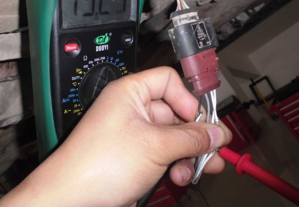
Probe the Wires:
Examine the wiring harness and identify the four wires: Heater+, Heater-, Signal, and Ground. Refer to the sensor's color code or consult your vehicle's service manual if needed.
Connect the multimeter probes to the Signal wire and the Ground wire. Ensure the polarity is correct (positive probe to Signal, negative probe to Ground).
Check for Voltage:
With the vehicle running (or ignition in the "On" position), observe the multimeter reading. A healthy O2 sensor should produce a fluctuating voltage signal that switches between approximately 0.1V and 0.9V.
The voltage signal should oscillate rapidly between rich (higher voltage) and lean (lower voltage) air-fuel mixtures.
Check the Heater Circuit:
Disconnect the multimeter probes from the Signal and Ground wires.
Connect the probes to the Heater+ and Heater- wires.
Measure the voltage across these wires. A properly functioning O2 sensor should show a voltage reading (typically 12V) indicating that the heater circuit is receiving power.
Visual Inspection:
Examine the physical condition of the sensor. Look for signs of damage or contamination, such as soot or oil deposits on the sensor tip.
Reconnect the Sensor:
After testing, reconnect the O2 sensor to its electrical connector.
Clear Error Codes (if needed):
If you were testing the O2 sensor due to a fault code, you may need to clear the error codes from the vehicle's ECU using an OBD-II scanner.
Read More:
What Happens If You Disconnect Throttle Position Sensor
Crankshaft Position Sensor Location
Temporary Fix for Crankshaft Position Sensor
How to Test Crankshaft Sensor with Multimeter
Where Is the Knock Sensor Located
How to Start a Car with a Bad Crankshaft Sensor
How to Start a Car with a Bad Crankshaft Sensor
How does the Oxygen Sensor OSS-2 Effectively Improve Vehicle Exhaust Pollution Emissions
Where are Radar Sensors on Mercedes
How Many Sensors Are In a Car【Types & Functions】
How to Delete O2 Sensors from ECM
How Many O2 Sensors Does a Car Have
4 Wire Oxygen Sensor Wiring Diagram
Can a Bad O2 Sensor Cause a Misfire
How to Reset a Mass Air Flow Sensor
Can I Use a Downstream Oxygen Sensor for Upstream
Latest Blogs
Popular Manufacturers