IGBT vs GTO: Difference Between IGBT and GTO
Sep 26, 2023 View: 2683

Catalog:
Introduction
Gate-Turn-Off Thyristor (GTO)
FAQ about GTO
Insulated Gate Bipolar Transistor (IGBT)
FAQ about IGBT
Difference Between IGBT and GTO
Conclusion
Introduction
The world of power electronics is driven by the relentless quest for efficiency, precision, and control in managing electrical energy. Two key players in this arena are the IGBT (Insulated Gate Bipolar Transistor) and the GTO (Gate Turn-Off Thyristor). While both devices serve critical roles in high-power applications, they possess distinct characteristics that set them apart. In this comparison, we delve into the fundamental differences between IGBT and GTO, exploring their structures, operational principles, and applications.
Gate-Turn-Off Thyristor (GTO)
GTO (Gate-Turn-Off Thyristor) is a significant branch of thyristor technology, capable of achieving gate control for the purpose of shutdown. Therefore, it is also referred to as a Gate-Turn-Off Thyristor. This device is an improved version of the conventional thyristor, allowing active shutdown by applying negative pulse currents to the gate, hence classifying it as a fully controllable device.
The Gate-Turn-Off Thyristor possesses the self-turn-off capability while retaining the characteristics of a conventional thyristor. When a positive voltage is applied to the anode and a positive trigger current is applied to the gate, the GTO conducts current. However, in the conducting state, a sufficiently large reverse-trigger pulse current applied to the gate can transition the GTO from the conducting state to a fully blocking state.
The GTO (Gate Turn-Off) device exhibits a distinctive structure composed of four alternating P-type and N-type semiconductor layers, setting it apart from conventional thyristors. In a detailed examination, GTO can be regarded as a coupled pair of transistors, featuring one in a PNP configuration and the other in an NPN configuration, mirroring the arrangement seen in typical thyristors. The GTO is equipped with three essential terminals, namely 'anode,' 'cathode,' and 'gate.'
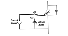
GTO Thyristor ON/OFF Circuit

GTO construction and circuit symbol
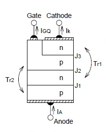
GTO transistor base unit

V-I Characteristics
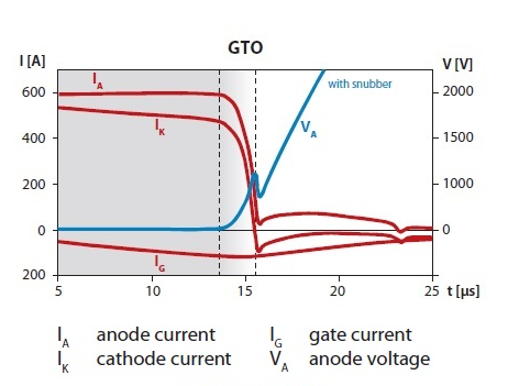
Voltage and current waveforms when GTO structure is turned off
FAQ:
Can GTO be turned off?
A GTO (Gate Turn-Off Thyristor) can be turned off at any time by applying a gate signal equal to 0 or a gate signal with a negative polarity.
How can a conducting GTO be turned off?
Bias the gate terminal negatively with respect to the cathode. This means applying a voltage or signal to the gate terminal that is lower in voltage than the cathode terminal.
When the gate terminal is negatively biased, it creates an electric field that causes the holes injected from the anode (during the conducting state) to be extracted from the P base region of the GTO. These holes are drawn away from the gate region, disrupting the flow of current between the anode and the cathode.
As the holes are extracted, the GTO transitions from its conducting state to a blocking state. It effectively turns off, and the current flow between the anode and the cathode is interrupted.
By applying a negative gate bias, you essentially remove the carriers (holes) responsible for maintaining conduction, allowing the GTO to be turned off at any time during its operation.
What is a gate turn off thyristor used for?
GTOs are used in high-power and high-voltage applications that demand precise control, rapid switching, and efficient power conversion. Their ability to turn off high currents and handle high voltages makes them valuable components in power electronics and industrial systems.
Is the GTO gate turn off thyristor a PNP?
A GTO (Gate Turn-Off Thyristor) is not a PNP (Positive-Negative-Positive) transistor. It is a four-layer, three-terminal semiconductor device with a different structure compared to traditional transistors.
The structure of a GTO consists of four layers of alternating P-type and N-type semiconductor materials, forming a PNPN structure. It has three terminals: Anode (A), Cathode (K), and Gate (G). The four layers are typically labeled as P+ (Anode side), N-, P+, and N+.
What is the difference between SCR and GTO?
The main difference between a GTO (Gate Turn-Off Thyristor) and an SCR (Silicon-Controlled Rectifier) lies in their internal structure.
GTO is a four-layer, three-terminal semiconductor device with a PNPN structure. The anode of a GTO is made up of an initial P+ layer, but it also has n+ type fingers diffused into this P+ layer.
GTOs have the unique capability to be turned off at any time by applying a gate signal equal to 0 or a negative gate signal.
SCR is also a four-layer, three-terminal semiconductor device with a PNPN structure. The anode of an SCR is primarily made up of a P+ layer, without the presence of n+ fingers.
While both GTOs and SCRs have a similar PNPN structure and are used for power switching applications, the presence of n+ fingers diffused into the anode is a distinguishing feature of GTOs. This feature allows GTOs to be turned off at any time, providing greater control and flexibility in certain applications. SCRs, on the other hand, typically rely on zero-crossing current to turn off.
What is the advantage of GTO thyristor?
Fast switching speeds.
Precise turn-off control.
Bidirectional conduction (AC and DC).
High current and voltage handling.
Robustness and reliability.
Versatility in high-power applications.
Efficiency in power conversion.
Insulated Gate Bipolar Transistor (IGBT)
The Insulated Gate Bipolar Transistor (IGBT) is a semiconductor device featuring a trio of terminals designated as 'Emitter,' 'Collector,' and 'Gate.' This transistor variant stands out for its capability to manage substantial power levels and its impressive switching speed, which contributes to its high efficiency. The inception of IGBTs into the market dates back to the 1980s.

Symbol of IGBT
IGBTs effectively amalgamate the favorable attributes of both Metal-Oxide-Semiconductor Field-Effect Transistors (MOSFETs) and Bipolar Junction Transistors (BJTs). They are gate-driven akin to MOSFETs while exhibiting current-voltage characteristics reminiscent of BJTs. Consequently, IGBTs offer the advantages of accommodating high current levels while simultaneously facilitating ease of control. IGBT modules, comprising multiple individual devices, exhibit the capability to handle power in the kilowatt range, showcasing their prowess in power electronics applications.
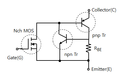
Internal equivalent circuit of IGBT
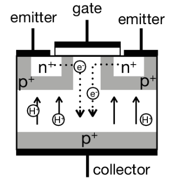
Schematic of Insulated Gate Bipolar Transistor
FAQ:
What is the advantage of IGBT?
-
High voltage and current handling capabilities
-
High input impedance
-
Low voltage high current switching
-
voltage control device
-
Simple gate drive circuit
-
Easy to switch on and off
-
Low on-resistance
-
High current density
-
High power gain
-
High switching speed
-
Low control voltage high current switching
-
Bipolar properties enhance conductivity
Read more: https://www.nevsemi.com/blog/what-is-the-advantage-of-igbt
What is an IGBT inverter?
An IGBT inverter refers to an electrical inverter that utilizes Insulated Gate Bipolar Transistors (IGBTs) as the switching devices within its circuitry. Inverters, in general, are electronic devices that convert direct current (DC) into alternating current (AC).
First, the IGBT inverter typically rectifies the incoming AC power source (usually from the mains or a generator) into DC power. This DC power is then stored in capacitors or used directly to feed the inverter.
The DC power is then fed into the IGBT inverter circuit, where the IGBTs play a crucial role. IGBTs switch the DC voltage on and off at a high frequency, creating a pulsed DC waveform.
The pulsed DC waveform is smoothed out using filters to reduce harmonics and provide a cleaner DC signal.
The filtered DC is then used to generate a high-quality sinusoidal AC output waveform. The IGBTs switch rapidly to create the AC waveform, which can be precisely controlled in terms of frequency, voltage, and phase.
How Do IGBT works?
IGBT works by controlling the flow of electrical current between its collector and emitter terminals using a voltage applied to its gate terminal.
What is the difference between SCR and IGBT?
SCR is primarily used for unidirectional switching and has specific requirements for turning off, while IGBT is a bidirectional, voltage-controlled switch with faster switching speeds, making it more versatile in modern power electronics applications.
Read more: https://www.nevsemi.com/blog/igbt-vs-thyristor
Is IGBT controlled by current or voltage?
IGBTs (Insulated Gate Bipolar Transistors) are primarily controlled by voltage, specifically the voltage applied to their gate terminal. To turn on an IGBT, you apply a positive voltage to its gate terminal relative to its emitter terminal. This creates an electric field in the device, allowing current to flow from the collector to the emitter. The voltage at the gate terminal controls the conductivity of the IGBT, making it act as a voltage-controlled switch.
Is IGBT AC or DC output?
IGBTs (Insulated Gate Bipolar Transistors) can be used to control both AC (Alternating Current) and DC (Direct Current) output, depending on the application and the circuit configuration in which they are used.
Difference Between IGBT and GTO
|
Aspect |
IGBT |
GTO |
|
Full Form |
Insulated Gate Bipolar Transistor |
Gate-Turn-Off Thyristor |
|
Advantages |
- High switching speed |
- High voltage tolerance |
|
- Ease of control |
- Large current-carrying capacity |
|
|
- High power efficiency |
- Robust surge current handling |
|
|
- Suitable for various voltage |
capability |
|
|
and current ratings |
- Can be actively turned off |
|
|
using negative pulses |
||
|
Disadvantages |
- May have higher conduction |
- Slower switching speed |
|
losses compared to GTO |
- Gate-triggered for turn-on, |
|
|
- Typically lower voltage |
but not for turn-off |
|
|
tolerance than GTO |
- May require complex drive |
|
|
- Limited surge current handling |
circuitry for reliable |
|
|
capability |
turn-off |
|
|
Applications |
- Motor drives |
- High-power rectification |
|
- Variable frequency drives |
- Inverters for renewable |
|
|
- Uninterruptible power supplies |
energy systems |
|
|
- Induction heating |
- High-voltage DC transmission |
|
|
- Welding equipment |
systems |
|
Aspect |
IGBT |
GTO |
|
Terminal Names |
Emitter, Collector, Gate |
Anode, Cathode, Gate |
|
Gate Control |
Requires continuous gate voltage |
Requires a pulse for switching |
|
Device Classification |
Type of transistor |
Type of thyristor |
|
Number of PN Junctions |
One PN junction |
Three PN junctions |
|
Typical Applications |
Motor drives, Variable frequency drives, UPS |
High-power rectification, DC transmission systems |
|
Gate Control Complexity |
Relatively simpler gate control |
Requires external devices and complex control circuits |
|
Turn-On and Turn-Off |
Easily controllable |
Requires external devices for reliable turn-off and on |
Conclusion
In the realm of high-power semiconductor devices, the choice between IGBT and GTO hinges on the specific demands of the application at hand. The IGBT, with its voltage-controlled operation and faster switching speeds, excels in a wide array of applications, offering efficiency and precision. On the other hand, the GTO, with its unique gate turn-off capability, is indispensable in scenarios requiring precise control over turn-off timing. As technology advances, these devices continue to evolve, pushing the boundaries of what is achievable in power electronics.
Read More:
Difference Between BJT, MOSFET and IGBT: BJT vs MOSFET vs IGBT
IGCT vs. IGBT: What Are the Difference
IGBT vs GTO: Difference Between IGBT and GTO
IGBT Structure, Characteristics and Working Principle
Application of IGBT and IGBT Application Examples
IGBT Symbol Diagram, Characteristics, Circuit
Global IGBT Shortage: Cause & Future Outlook
IGBT Rectifier: All You Want to Know
IGBT Types: Understanding the Basics
How to Test an IGBT with A Multimeter
Difference Between IGBT and MOSFET (IGBT vs MOSFET)
What is the Advantage of IGBT
Difference Between IGBT and Thyristor
Latest Blogs
Popular Manufacturers