How to Test an IGBT Using A Multimeter
Jul 10, 2023 View: 12526
Introduction
Testing your Insulated Gate Bipolar Transistor (IGBT) is of utmost importance. By conducting testing, you can identify any potential faults or weaknesses in the IGBT, allowing for timely repairs or replacements. This not only prevents unexpected failures but also helps optimize the performance and longevity of your electrical system.
Catalog:
How to Test an IGBT using A Multimeter
How to Use a Multimeter for IGBT Pin Identification and Testing
Steps for testing IGBT with multimeter
How do I know if my IGBT is good or bad
How to Test an IGBT using A Multimeter
Preparation
Power Off: First, you need to make sure that the power to the circuit or device containing the IGBT is turned off and disconnected.
Set Multimeter: Then, you need to set your multimeter to the diode test mode or the resistance mode (ohmmeter). The multimeter should be properly calibrated so that it can function correctly.
Identify the IGBT Pins: Last but not least, you need to identify the three pins of the IGBT: emitter (E), collector (C), and gate (G). You can refer to the diagram for pin identification if necessary.
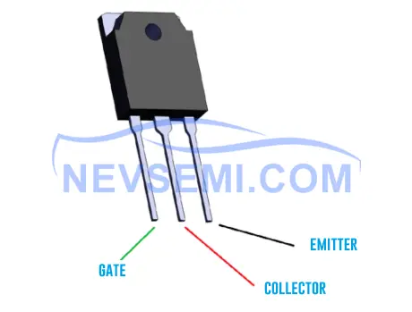
Diode Test Mode
1. Connect the multimeter's positive lead (red probe) to the collector pin (C) of the IGBT.
2. Connect the multimeter's negative lead (black probe) to the emitter pin (E) of the IGBT.
3. Observe the multimeter reading.
In the diode test mode, a good IGBT will typically show a voltage drop around 0.6 to 0.7 volts in one direction (forward biased) and indicate an open circuit or a very high resistance value in the reverse direction.
Resistance Mode (Ohmmeter)
1. Disconnect the IGBT from the circuit or device.
2. Set the multimeter to the resistance mode (ohmmeter).
3. Connect the multimeter's positive lead (red probe) to the collector pin (C) of the IGBT.
4. Connect the multimeter's negative lead (black probe) to the emitter pin (E) of the IGBT.
5. Note the resistance reading on the multimeter.
A low resistance value (typically a few ohms) indicates a functioning IGBT, while a very high resistance or an open circuit indicates a faulty IGBT.

How to Use a Multimeter for IGBT Pin Identification and Testing
IGBT (Insulated Gate Bipolar Transistor) is a vital semiconductor device, and to correctly identify its pins and assess its quality, you can use either an analog or a digital multimeter. Before performing IGBT pin identification and testing, it's essential to short-circuit the three pins of the IGBT to ensure accuracy. Here are the specific steps:
1. Pin Identification
1.1 Using an Analog Multimeter
Set the analog multimeter to the Rx1k range.
To identify the pins, measure the resistance. If the resistance of one pin is infinite (extremely high) compared to the other two, and changing the test leads doesn't alter this, you can identify this pin as the gate (G).
Repeat a similar measurement for the other two pins. If one measurement shows infinite resistance and the other shows lower resistance, the pin touched by the red probe is the collector (C), and the one touched by the black probe is the emitter (E).
1.2 Using a Digital Multimeter
Set the digital multimeter to the diode mode.
Fix the red probe to one pin and sequentially touch the other two pins. If both measurements display around 0.7V, the red probe is on the gate (G), and the IGBT is an N-channel type.
If both measurements show an excessively high voltage, it still indicates that the red probe is on the gate (G), but the IGBT is a P-channel type.
If one measurement displays 0.3-0.6V and the other shows a high voltage, the red probe isn't on the gate, and you should try other pins.
2. Testing IGBT Quality
Set the analog multimeter to the Rx10k range.
Connect the black probe to the IGBT's collector (C) and the red probe to the emitter (E). The pointer on the multimeter should be at zero.
Simultaneously touch the gate (G) and the collector (C) with your fingers; this will turn on the IGBT. The multimeter's pointer will shift towards the lower resistance direction and stabilize.
Next, touch the gate (G) and the emitter (E) with your fingers; this will turn off the IGBT. The multimeter's pointer will return to zero. If the actual results match these descriptions, the tested IGBT is working correctly.
3. Checking for the Presence of a Snubber Diode
Use the analog multimeter on the Rx1k range or the digital multimeter in diode mode to measure the resistance between the IGBT's G-E and G-C.
For a normal IGBT, resistance between G-C and G-E should be infinite.
For an IGBT containing a snubber diode, there will be approximately 4kΩ of forward resistance between E-C.
Finally, use the analog multimeter with the red probe on the C pin and the black probe on the E pin. If the measured resistance is around 3.5kΩ, it indicates an IGBT with a snubber diode; if it's around 50kΩ, the IGBT does not contain a snubber diode.
Important Notes:
- Use the Rx10k range to assess IGBT quality, as ranges below Rx1k may not provide sufficient voltage to turn on the IGBT, leading to inaccurate results.
- Due to the sensitivity of IGBTs to external electromagnetic fields and static electricity, use extra caution when using a digital multimeter. Ground yourself and ensure static discharge before touching IGBT pins.
- In all cases, follow safety procedures and exercise caution while operating the equipment.
Steps for testing IGBT with multimeter
IGBT modules are essential components in power electronic devices. Whether during initial deployment, post-maintenance, or product acceptance phases, module testing is necessary. Here, we will outline the steps for testing the IGBT module FF450R12KT4 using a multimeter.
Tools:
Digital multimeter
Analog multimeter
IGBT module
Steps:
1. The IGBT module and its pins are as follows:


2. To test the IGBTs in the lower bridge arm, start by short-circuiting pins 6 and 7 to discharge them. This is primarily to prevent pins 6 and 7 from remaining in the CE-conductive state in case of overload in the trigger power supply.
3. Next, use a multimeter to measure the conduction of the internal parallel diodes. In this step, you have the option of using either a digital multimeter or an analog multimeter. Follow these specific procedures:
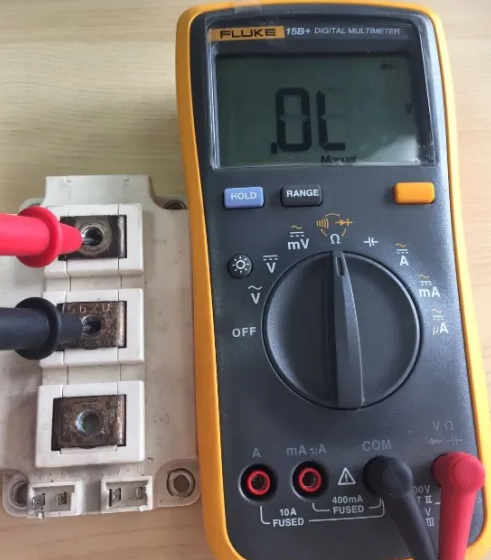
For a digital multimeter, refer to Figures 1 and 2. Set the multimeter to the diode testing mode and connect the red probe to pin 2 and the black probe to pin 1. If the displayed diode voltage drop is 0.3V, it indicates conduction. If you reverse the probe connections, with the red probe on pin 1 and the black probe on pin 2, and there's no conduction indicated, it means no conduction is present.
For an analog multimeter, as shown in Figures 3 and 4, set the multimeter to the R╳10kΩ range. Connect the black probe to pin 2 and the red probe to pin 1. If it shows a very low resistance, it signifies conduction. If you reverse the probe connections, with the black probe on pin 1 and the red probe on pin 2, and it displays infinite resistance, it means there's no conduction. If you observe any results contrary to the above descriptions, it suggests an abnormality in the IGBT.


4. To test the conduction state of the IGBT, use an analog multimeter and set it to the R╳10kΩ range. Connect the black probe to pin 1 and the red probe to pin 2. If it shows infinite resistance (see Figure 1), then short-circuit the black probe with pin 6 (i.e., apply a positive voltage to the gate, which can be done by touching it with two fingers from one hand). You will see the needle swing significantly and hold steady (as shown in Figure 2). Next, short-circuit the red probe with pin 6 (or pins 6 and 7, i.e., apply a low level to the gate, which can also be done by touching it with two fingers from one hand). At this point, the needle will return to its original position.


5. Use the multimeter to measure the conduction state between 1 and 6, 6 and 7, and 7 and 2 individually. In normal circumstances, there should be no conduction.

6. By following steps 2 and 5, you can assess the operational state of the IGBTs in the upper bridge arm.
How do I know if my IGBT is good or bad
To determine the status of an IGBT module, two key characteristics need to be considered: Turn-off characteristics and Turn-on characteristics.
- Measuring Turn-off Characteristics
When measuring the turn-off characteristics of an IGBT module, start by short-circuiting the gate and emitter (G, E) to ensure the gate capacitance is discharged. If the measurement shows that there is no conduction between the collector (C) and emitter (E), but conduction is observed from E to C (due to the built-in freewheeling diode), it indicates that the turn-off characteristics of the IGBT are normal.
- Measuring Turn-on Characteristics
When measuring the turn-on characteristics of the IGBT module, begin by using the resistance range of the multimeter and providing the built-in 9V power supply to charge the gate and emitter (G, E). If the measurement shows conduction from C to E and also from E to C, it indicates that the turn-on characteristics of the IGBT are normal.
By following these steps, you can use a multimeter to assess the status of the IGBT module and ensure that both its turn-off and turn-on characteristics are functioning as expected. This helps ensure the proper operation of the IGBT module within electronic circuits or systems.
Conclusion
Testing and ensuring optimal performance of your IGBT is crucial. The IGBT plays a vital role in power electronics. Through visual inspection, measuring electrical parameters, assessing gate drive and switching characteristics, and testing under stress conditions, potential faults can be identified. However, this multimeter test can only provide limited information about the IGBT's functionality. To obtain a more comprehensive assessment of the IGBT, additional tests such as gate drive testing, switching performance analysis, and so on are recommended.
Read More:
Difference Between BJT, MOSFET and IGBT: BJT vs MOSFET vs IGBT
IGCT vs. IGBT: What Are the Difference
IGBT vs GTO: Difference Between IGBT and GTO
IGBT Structure, Characteristics and Working Principle
Application of IGBT and IGBT Application Examples
IGBT Symbol Diagram, Characteristics, Circuit
Global IGBT Shortage: Cause & Future Outlook
IGBT Rectifier: All You Want to Know
IGBT Types: Understanding the Basics
How to Test an IGBT with A Multimeter
Difference Between IGBT and MOSFET (IGBT vs MOSFET)
What is the Advantage of IGBT
Difference Between IGBT and Thyristor
Previous: Difference Between IGBT and Thyristor 【IGBT vs Thyristor】
Latest Blogs
Popular Manufacturers