Difference Between IGBT and Thyristor 【IGBT vs Thyristor】
Jul 07, 2023 View: 6070
Introduction
IGBTs and thyristors share several similarities as semiconductor devices used for current control. Both feature a 'gate' and are frequently compared due to these commonalities. However, they differ in terms of applications and their respective advantages and disadvantages.
To facilitate your understanding of the similarities and distinctions between these devices, we have prepared a comprehensive guide comparing IGBTs and thyristors. Let's delve into it and explore their characteristics in detail!
Difference Between IGBT and Thyristor 【IGBT vs Thyristor】
|
Aspect |
Thyristor |
IGBT |
|
Definition |
A four-layer semiconductor device with a P-N-P-N structure |
An insulated gate bipolar transistor combining features from bipolar transistors and MOSFETs |
|
Terminals |
Anode, cathode, gate |
Emitter, collector, gate |
|
Layers |
Four layers |
Three layers |
|
Junction |
PNPN structure |
NPN structure |
|
Modes of operation |
Reverse blocking, forward blocking, forward conducting |
On-state, off-state |
|
Design structure |
Coupled transistors (PNP and NPN) |
Combined bipolar and MOSFET features |
|
Carrier source |
Two sources of carriers |
One source of carriers |
|
Turn-on voltage |
N/A |
Low gate voltage required |
|
Turn off loss |
Higher |
Lower |
|
Plasma density |
Higher |
Lower |
|
Operating frequency range |
Suitable for line frequency, typically lower |
Suitable for high frequencies, typically higher |
|
Die Size and Paralleling Requirements |
Larger die size, can be manufactured as monolithic devices up to 6" in diameter |
Smaller die size, often paralleled in a package |
|
Power range |
Suitable for high power applications |
Suitable for medium power applications |
|
Control requirements |
Requires gate current |
Requires continuous gate voltage |
|
Value for money |
Cost-effective |
Relatively higher cost |
|
Control method |
Pulse triggering |
Gate voltage control |
|
Switching speed |
Slower |
Faster |
|
Current switching capability |
High |
Moderate |
|
Control current |
High current drive |
Low current drive |
|
Voltage capability |
High voltage handling |
Lower voltage handling |
|
Power loss |
Higher power dissipation |
Lower power dissipation |
|
Application |
High voltage, robustness |
High-speed switching, efficiency |
Definition (SCR vs IGBT)
A thyristor, also known as a silicon-controlled rectifier (SCR), is a four-layer semiconductor device with a P-N-P-N structure. It consists of three PN junctions and functions as a switch for controlling electric power and alternating currents. The thyristor can be triggered into conduction by applying a pulse to the gate terminal. Once triggered, it remains conducting until the forward current drops below a certain threshold level.
Read more: https://en.wikipedia.org/wiki/Thyristor
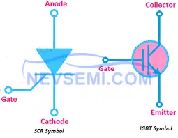
SCR symbol
An Insulated Gate Bipolar Transistor (IGBT) is a three-layer semiconductor device that combines the characteristics of bipolar transistors and Metal-Oxide-Semiconductor Field-Effect Transistors (MOSFETs). It is designed for power control applications and features a MOSFET input structure and a bipolar power output structure. The IGBT provides high voltage capabilities and low on-state power losses, making it suitable for high-power switching applications. It requires a continuous gate voltage to maintain conduction, but only a small gate current is needed for control.
Read more: https://en.wikipedia.org/wiki/Insulated-gate_bipolar_transistor

IGBT symbol
Terminals
Thyristor
Anode: The anode is the positive terminal of the thyristor. It is connected to the P-layer of the device and is the terminal through which the current enters the device during conduction.
Cathode: The cathode is the negative terminal of the thyristor. It is connected to the N-layer of the device and is the terminal through which the current exits the device during conduction.
Gate: The gate is the control terminal of the thyristor. It is connected to the inner P-type semiconductor layer between the two NPN transistors. The gate terminal controls the triggering and turning off of the thyristor by applying or removing a control pulse.
IGBT
Emitter: The emitter is the terminal through which the majority charge carriers (electrons in an N-channel IGBT or holes in a P-channel IGBT) enter or exit the device.
Collector: The collector is the terminal through which the majority charge carriers (electrons in a P-channel IGBT or holes in an N-channel IGBT) exit or enter the device.
Gate: The gate is the control terminal of the IGBT. It is insulated from the other terminals and is used to control the conductivity of the device. By applying a voltage to the gate, the IGBT can be turned on or off.
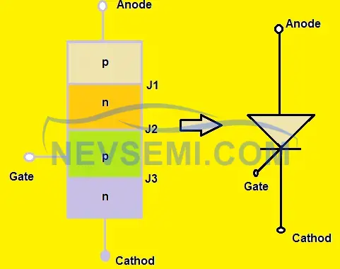
Layers
The thyristor is composed of four layers in a P-N-P-N structure. These layers are formed by alternating P-type (positive) and N-type (negative) semiconductor materials. The layers are arranged in such a way that they form three P-N junctions within the device. The middle P-layer is shared by both transistors in the structure, creating an interconnected configuration.
The IGBT is a three-layer semiconductor device. It consists of a P-type (positive) layer, an N-type (negative) layer, and an N+ (highly doped N-type) layer. The P-N junction between the P-type and N-type layers forms the bipolar transistor section, while the N+ layer and the N-type layer form the MOSFET section. The MOSFET section, with its insulated gate, controls the conductivity of the bipolar transistor section, enabling the IGBT to switch between on and off states.
Junction
The thyristor has multiple PN junctions within its four-layer structure. These PN junctions are formed between the adjacent P-type (positive) and N-type (negative) semiconductor layers. Specifically, the thyristor consists of two PN junctions: one between the first P-layer and the adjacent N-layer, and another between the second P-layer and the adjacent N-layer. These PN junctions play a crucial role in controlling the flow of current through the device during different modes of operation.
The IGBT contains both PNP (positive-negative-positive) and NPN (negative-positive-negative) junctions. The PNP junction is formed between the P-type (positive) layer and the adjacent N-type (negative) layer, while the NPN junction is formed between the N-type layer and the adjacent P-type layer. These junctions are essential for the bipolar transistor section of the IGBT, which provides the current amplification capability. The NPN junction controls the flow of majority carriers (electrons) in the N-channel, while the PNP junction controls the flow of majority carriers (holes) in the P-channel.
Modes of Operation
Reverse Blocking Mode: In this mode, the thyristor blocks the flow of current in the reverse direction. The PN junctions within the thyristor prevent the flow of positive current from the anode to the cathode.
Forward Blocking Mode: In this mode, the thyristor blocks the flow of current in the forward direction. The NP junctions within the device prevent the flow of negative current from the cathode to the anode.
Forward Conducting Mode: This is the mode in which the thyristor conducts current in the forward direction. Once triggered by a pulse applied to the gate terminal, the thyristor enters the forward conducting mode, allowing the current to flow from the anode to the cathode. It remains in this conducting state until the forward current drops below a specific threshold called the "holding current."
Unidirectional Operation: IGBTs can only switch current in the forward direction. When the IGBT is turned on by applying a voltage to the gate terminal, it allows the current to flow from the emitter to the collector, similar to a bipolar transistor. However, unlike a bidirectional device like a thyristor, the IGBT does not allow current to flow in the opposite direction. It behaves as a unidirectional switch for current control.
Carrier Source
Thyristors have two sources of carriers, one for each of the two NPN transistors in its structure. When the thyristor is triggered into conduction, both the NPN transistors contribute carriers to maintain the flow of current through the device. The carriers, either electrons or holes depending on the doping type, are responsible for the conduction of electric current.
IGBTs have one source of carriers, which is either electrons or holes depending on the device's doping type. The carriers are injected into the N-channel or P-channel region of the device through the emitter terminal. The injected carriers then flow through the channel region to establish the current path between the collector and emitter terminals.
Turn-On Voltage
To initiate conduction in a thyristor, a pulse or trigger voltage must be applied to the gate terminal. The gate voltage pulse triggers the thyristor, causing it to transition from the blocking state to the conducting state. Once triggered, the thyristor remains conducting until the forward current drops below the holding current level.
In contrast to thyristors, IGBTs require a continuous gate voltage supply to maintain conduction. Once the gate voltage is applied, the IGBT allows current to flow from the emitter to the collector. The gate voltage must be maintained throughout the desired conduction period. However, it's worth noting that the gate voltage required for an IGBT to maintain conduction is typically lower than the voltage required to trigger a thyristor.
Turn-Off Loss
Thyristors typically experience higher turn-off losses compared to IGBTs. When a thyristor is triggered to turn off, the high plasma density within the device requires the removal of a significant amount of charge. This process of removing the charge during turn-off results in higher turn-off losses. The high plasma density requires more time and energy to recombine the carriers and extinguish the current flow.
IGBTs generally exhibit lower turn-off losses compared to thyristors. The turn-off process in IGBTs involves the control of the gate voltage to decrease the conductivity of the device. Due to the lower plasma density in IGBTs, the charge removal process during turn-off is more efficient, resulting in lower turn-off losses. This characteristic contributes to the overall efficiency and performance of IGBT-based systems.
Plasma Density
Thyristors operate at a higher plasma density compared to three-layer transistors. Plasma density refers to the concentration of ionized charge carriers within a semiconductor device. In thyristors, the four-layer structure and the presence of multiple PN junctions result in a higher concentration of ionized carriers during operation. The higher plasma density in thyristors requires more charge to be removed during turn-off, leading to higher turn-off losses.
IGBTs, on the other hand, have lower plasma density compared to thyristors. The three-layer structure of IGBTs and the absence of additional PN junctions contribute to the lower concentration of ionized charge carriers. The lower plasma density in IGBTs allows for more efficient control of carrier injection and removal, resulting in improved switching characteristics and lower turn-off losses.
Operating Frequency Range
Thyristors are typically designed to operate at line frequency, which is the frequency of the power supply, commonly 50 Hz or 60 Hz. They are commonly used in applications where the frequency of the power source remains constant, such as in AC power transmission systems and industrial motor control. Thyristors are less applicable to variable speed drives, where the frequency may change dynamically.
IGBTs have a wider operating frequency range and can operate independently of the line or load frequency. They are commonly used in variable speed drives, such as motor control applications, where the frequency of the power source can be adjusted to control the speed of the motor. IGBTs can handle high-frequency switching operations, typically ranging from several kilohertz to several tens of kilohertz, allowing for precise control and efficient power conversion in various applications.
Die Size and Paralleling Requirements
Thyristors can be manufactured as monolithic devices with larger die sizes. They are available in larger sizes, with diameters of up to 6 inches. This larger die size allows for higher power handling capabilities and current ratings. Thyristors with larger die sizes are commonly used in high-power applications where the ability to handle high currents is crucial.
IGBTs, on the other hand, typically have smaller chip sizes compared to thyristors. The smaller chip size is advantageous for several reasons, including improved thermal management, higher switching speeds, and easier integration into compact electronic systems. To achieve higher power ratings, IGBTs are often paralleled in a package. Multiple smaller IGBT chips can be connected in parallel to increase the overall current-carrying capability and power handling capacity.
Power Range
Thyristors are well-suited for high power applications. Their robust construction and ability to handle high currents make them ideal for demanding power control requirements. Thyristors can efficiently handle power levels ranging from several kilowatts to several megawatts. They are commonly used in applications such as motor drives, high-power rectifiers, and AC power transmission systems.
IGBTs are suitable for a wide range of power applications, ranging from medium to high power levels. They offer excellent power handling capabilities while maintaining efficient operation. IGBTs are commonly used in medium to high-power applications such as industrial motor drives, uninterruptible power supplies (UPS), renewable energy systems, and electric vehicle powertrains. Their power ratings typically range from a few hundred watts to several megawatts.
Control Method
Thyristors are typically controlled using pulse triggering. To initiate conduction in a thyristor, a short-duration pulse or trigger signal is applied to the gate terminal. The pulse triggers the device and allows current to flow through the thyristor until the forward current drops below the holding current level. The pulse triggering method provides precise control over the thyristor's operation, allowing for accurate switching and power control.
IGBTs, on the other hand, are controlled using a continuous gate voltage supply. The gate voltage is continuously applied to the gate terminal to maintain conduction in the device. The gate voltage level determines the conductivity of the IGBT, allowing for precise control over the switching behavior and power flow. The continuous gate voltage supply ensures that the IGBT remains in the desired conducting or blocking state based on the gate voltage applied.
Switching Speed
Thyristors generally have slower switching speeds compared to IGBTs. The turn-on and turn-off times of thyristors are relatively longer due to the need for carrier recombination and removal during switching transitions. The process of removing the excess charge carriers and transitioning between conducting and blocking states takes a relatively longer time. As a result, thyristors are better suited for applications where slower switching speeds are acceptable, such as in power transmission systems and industrial motor control.
IGBTs offer faster switching speeds compared to thyristors. They are designed to facilitate rapid transitions between conducting and blocking states. The reduced carrier storage and removal times in IGBTs enable faster switching characteristics. This feature is advantageous in applications that require high-frequency switching, such as in variable speed motor drives, power inverters, and switching power supplies. The fast switching speeds of IGBTs contribute to higher system efficiency and improved control performance.
Power Loss
Thyristors typically have higher power dissipation compared to IGBTs. During operation, thyristors exhibit higher conduction losses due to the voltage drop across the device when it is conducting current. Additionally, thyristors have higher turn-off losses as a result of the higher plasma density and the need to remove charge carriers during the turn-off process. These losses contribute to increased power dissipation, which results in higher heat generation within the device. Proper thermal management is crucial when using thyristors in high-power applications to ensure safe and reliable operation.
IGBTs generally have lower power dissipation compared to thyristors. The conduction losses in IGBTs are relatively lower due to their lower on-state voltage drop when conducting current. Additionally, IGBTs exhibit lower turn-off losses compared to thyristors, resulting in reduced power dissipation during the switching process. The lower power dissipation in IGBTs leads to improved overall system efficiency and reduced thermal stress on the device. Efficient thermal management is still important to maintain the IGBTs' temperature within safe operating limits.
Application
Thyristors find applications in line commutated systems where they operate at the line frequency. They are commonly used in high-power applications such as AC power transmission systems, industrial motor control, and static switches. Thyristors are also suitable for motor starters and AC induction motor speed control in industrial segments, particularly for fan control. Additionally, thyristors are advantageous in applications that require a high peak-to-average current rating due to their robustness and ability to handle high currents.
IGBTs have widespread applications in various industries. They are commonly used in frequency converters for converting AC to DC or vice versa. IGBTs are extensively employed in motor drives, enabling efficient control of motor speed and torque in industrial and automotive applications. Switch-mode power supplies utilize IGBTs for efficient power conversion. Variable speed control systems, such as those used in HVAC systems and industrial pumps, make use of IGBTs for precise control over motor speed. Furthermore, IGBTs are employed in traction motor control for electric vehicles and trains, facilitating efficient and reliable propulsion.
Conclusion (SCR vs IGBT)
IGBTs and thyristors are both semiconductor devices used for current control. While they share similarities such as having a gate and controlling currents, there are key differences between them. IGBTs combine features from bipolar transistors and MOSFETs, offering fast switching speeds and low power dissipation. They are ideal for high-speed switching applications. On the other hand, thyristors, such as SCRs, operate in multiple modes and are robust, reliable, and cost-effective, making them suitable for high-voltage applications. Understanding these differences is crucial in selecting the appropriate device for specific power electronic applications.
Read More:
Difference Between BJT, MOSFET and IGBT: BJT vs MOSFET vs IGBT
IGCT vs. IGBT: What Are the Difference
IGBT vs GTO: Difference Between IGBT and GTO
IGBT Structure, Characteristics and Working Principle
Application of IGBT and IGBT Application Examples
IGBT Symbol Diagram, Characteristics, Circuit
Global IGBT Shortage: Cause & Future Outlook
IGBT Rectifier: All You Want to Know
IGBT Types: Understanding the Basics
How to Test an IGBT with A Multimeter
Difference Between IGBT and MOSFET (IGBT vs MOSFET)
What is the Advantage of IGBT
Difference Between IGBT and Thyristor
 FAQ
FAQ
- What is the difference between MOSFETs and IGBTs? IGBT transistor vs MOSFET
- Comparatively, low voltage MOSFETs exhibit significantly lower 'ON' resistance when compared to IGBTs. These characteristics render MOSFETs exceptionally suitable for tasks like switching power supplies and applications functioning at around 100 kHz, coupled with low current density demands. Conversely, IGBTs emerge as the superior choice in scenarios like AC drives, where operations occur below 20 kHz while maintaining high current density.
- What is IGBT Inverter
- Insulated Gate Bipolar Transistors, often abbreviated as IGBT, refers to a crucial component found in Weldclass Inverter welding machines. These high-speed switching devices play a pivotal role in enabling precise voltage regulation. While some inverter machines still employ traditional MOSFET technology or transistors, the IGBT technology is adopted for its advanced performance attributes.
- How Does an IGBT Work
- When a positive gate-to-emitter voltage (UGE) is applied, the MOSFET is activated. Subsequently, the collector-connected voltage facilitates the passage of base current through both the bipolar transistor and the MOSFET. This leads to the activation of the bipolar transistor, allowing the load current to smoothly traverse.
- How Does a Thyristors Work
- To avert power supply interruptions, a Zener diode is incorporated at the thyristor gate, ensuring seamless operation. Upon surpassing the Zener voltage threshold, the thyristor discontinues power supply output to ground. This triggers the activation of circuit breakers or fuses located upstream from the power supply, guaranteeing robust protection.
Latest Blogs
Popular Manufacturers