IGBT Rectifier: All You Want to Know
Aug 01, 2023 View: 5311
With the advancement of modern microelectronics, power components, and computer technologies, rectifier structures and their control methodologies have experienced rapid evolution. The progression has extended from traditional diode rectifiers and silicon-controlled rectifiers to sophisticated large-capacity IGBT rectifiers, all of which have found practical applications. The selection of rectification structures and the adoption of advanced control technologies are driven by diverse technical requirements.
In the context of power component current flow capacity and voltage resistance levels, the choice of a rectifier with a specific structure becomes pivotal in the design of transmission systems. This article will delve into the definition, working principles, applications, advantages, and other pertinent aspects of IGBT rectifiers.
What is an IGBT rectifier?
A rectifier is an electronic device that converts alternating current (AC) to direct current (DC), and is commonly used in power electronics for various applications such as motor drives, power supplies, and industrial equipment. Traditional rectifiers use diodes as switching elements. However, an IGBT rectifier is a rectification circuit that uses an insulated gate bipolar transistor (IGBT) as the main semiconductor switching device. IGBTs combine the properties of MOSFETs (Metal-Oxide-Semiconductor Field-Effect Transistors) and bipolar transistors, making them ideal for high-power applications requiring fast switching and high-voltage capabilities.
First of all, ordinary IGBT chips are unidirectional conduction components, and there are no diodes inside the IGBT chip (power MOSFETs have parasitic body diodes, but IGBTs do not). However, during packaging, the IGBT chip and the diode chip can be placed in the same package, so that the packaged components can achieve two-way conduction.
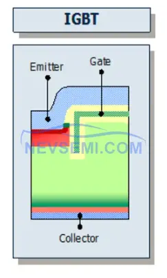

There is a reverse-conducting IGBT. The IGBT structure and the diode structure are made on the same chip, so that one chip can realize bidirectional current flow.

When measuring diodes, use the diode setting, not the resistance setting.
There are two types of rectification: uncontrolled rectification, semi-controlled rectification and controlled rectification. Uncontrolled rectification and semi-controlled rectification use diodes and thyristors. The ratio of DC voltage to AC power supply voltage in an uncontrolled rectifier circuit is fixed. The average load voltage of the semi-controlled rectifier circuit is adjustable, but the polarity cannot be changed.

Controlled rectification uses controllable power devices such as MOSFET or IGBT, and the average value and polarity of the DC rectified voltage are adjustable. The picture in the topic is a three-level circuit. When the power factor is -1, it works in the rectification state. When the power factor is +1, it works in the inverter state. The power device uses PWM modulation, and IGBT and anti-parallel diodes will participate in the work.
The Working Principle of IGBT Rectifier
Step 1: Rectification: Converts AC input to DC output.
Step 2: IGBT Control: Each IGBT in the bridge rectifier acts as a controlled switch. A strobe signal at the gate terminal of each IGBT controls its on and off state. When the IGBT is turned on, it conducts current, and when it is turned off, it prevents the flow of current.
Step 3: Phase Operation: The IGBT rectifier operates in synchronization with the phase of the input AC voltage waveform. During the positive half-cycle of each phase, the corresponding IGBT in the positive leg of the bridge turns on, allowing current to flow through it and the load. At the same time, the corresponding IGBT in the negative leg of the bridge is turned off.
Step 4: Bidirectional power flow: During the negative half cycle of each phase, the operation is reversed. The IGBT in the positive leg turns off, the IGBT in the negative leg turns on, and the current flows through the load in the opposite direction.
Step 5: Controlled Output: The timing and duration of the IGBT's gating signal determines the output voltage and current. By precisely controlling the switching of the IGBTs, the rectifier can regulate the output voltage and current.
Step 6: Energy buffering: IGBT rectifiers typically use DC link capacitors to store energy during the positive half cycle and release energy during the negative half cycle to reduce power fluctuations.
How PWM works in IGBT Rectifier VFD, PWM, STATCOM
Can IGBT be used as a rectifier?
Yes, IGBTs can be used as rectifiers. Although IGBTs are primarily used as high power switches, they can also be used as rectifiers. Typically, it is connected in a "bridge rectifier" configuration. A bridge rectifier circuit consists of four semiconductor devices arranged in a bridge, which can be either diodes or IGBTs.

What is a 3 phase rectifier with IGBT?
A three-phase rectifier with IGBT is a rectification circuit that converts three-phase alternating current (AC) into direct current (DC) using IGBTs as switching elements. Three-phase combination enables continuous DC output.
It usually uses a configuration called a "three-phase bridge rectifier". It consists of 6 IGBTs arranged in a bridge configuration to handle three-phase AC input. Each phase consists of two IGBTs connected in series, forming the positive and negative legs of the bridge.

Each IGBT operates in switching mode to control the flow of current from the AC input to the DC output. When the voltage on a particular phase is positive, the corresponding IGBT in the positive leg of the bridge becomes forward biased, allowing current to flow through it and the load (represented by the (+) and (-) DC outputs). When this phase voltage becomes negative, the corresponding IGBT in the negative leg becomes forward biased, allowing current to flow through the load in the opposite direction.

Three phase PWM regenerative boost rectifier
What are the advantages of an IGBT rectifier?
High efficiency
High frequency operation
High control ability and precision
Two-way conduction
Highly integrated
Low electromagnetic interference
High power applications
IGBT vs. SCR Rectifier
Why use an IGBT rectifier instead of a SCR rectifier?
Compared with SCR rectifiers, IGBT rectifiers can run continuously for 24 hours.
IGBT rectifier consumes at least 15% less power than SCR rectifier
The IGBT rectifier is less affected by power fluctuations, 100% output, no additional capacity is required.
The IGBT rectifier adopts AC-DC-AC-DC topology, 3-phase AC is first converted to DC, in which there are capacitors for energy charging and discharging, which will suppress power fluctuations.
The SCR rectifier does not have the function of energy buffering, it is directly affected by the power fluctuation of the grid.
The time required for IGBT rectifier plating is shortened by 40%.
Low grid pollution, power factor>0.93
Lower cost
|
Feature |
IGBT Rectifier |
SCR Rectifier |
|
Reliability |
High |
High |
|
Power Consumption |
At least 15% lower |
- |
|
Impact of Power Fluctuations |
Smaller |
Larger |
|
100% Output, No Extra Capacity |
Yes |
No |
|
Plating Time Reduction |
Shorter (40% reduction) |
- |
|
Size and Weight |
Smaller |
Larger |
|
Grid Pollution |
Low (Power Factor > 0.93) |
Higher |
|
Cost |
Lower |
- |
Overall, an IGBT rectifier works by using an IGBT as a controlled switch to rectify the AC input, regulate the output voltage, and enable bidirectional power flow.
Read More:
Difference Between BJT, MOSFET and IGBT: BJT vs MOSFET vs IGBT
IGCT vs. IGBT: What Are the Difference
IGBT vs GTO: Difference Between IGBT and GTO
IGBT Structure, Characteristics and Working Principle
Application of IGBT and IGBT Application Examples
IGBT Symbol Diagram, Characteristics, Circuit
Global IGBT Shortage: Cause & Future Outlook
IGBT Rectifier: All You Want to Know
IGBT Types: Understanding the Basics
How to Test an IGBT with A Multimeter
Difference Between IGBT and MOSFET (IGBT vs MOSFET)
What is the Advantage of IGBT
Difference Between IGBT and Thyristor
Latest Blogs
Popular Manufacturers